Installation of an AFR+ unit can be broken down into three categories. All installations should be performed in the following order:
Bosch O2 Sensor - Installed in the exhaust pipe in order to make AFR readings. Replaces factory narrowband sensor in some applications, but most applications require an O2 bung be welded into the exhaust pipe in a certain location. Locations are given in the PRODUCT section. EXPERT WELDER REQUIRED
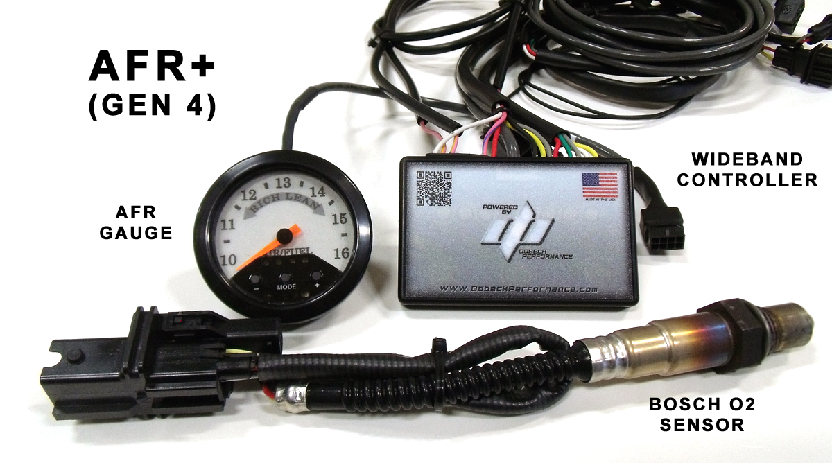
Wideband Controller - Contains harness connections to external parts and hardware to interpret input signals and generate output signals.
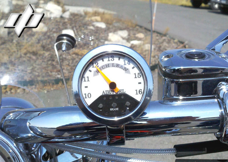
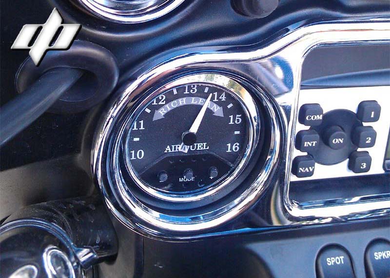
AFR Gauge - Installed on vehicle to allow easy viewing by user during operation. Shows current AFR value based on the O2 sensor input, provides four LEDs to understand the active fueling zones and has three push buttons to allow instantaneous adjustment on the vehicle without a computer.
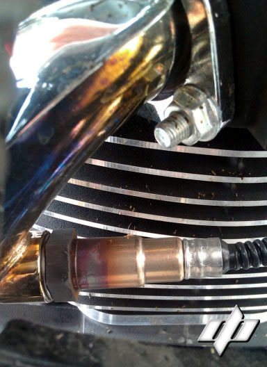
The first step in an AFR+ installation is determing where the O2 sensor will be installed. Some after-market exhausts already have an O2 bung installed. Some applications also just require the replacement of the stock narrowband O2 sensor. Other installations will require the welding of an O2 bung into the exhaust pipe. Dobeck supplies a flat O2 bung or a 45 degree O2 bung for all applications where the factory narrowband is NOT replaced. In these cases the O2 bung should be installed by a proficient welder. Operation of an AFR gauge relies on the proper installation of the oxygen sensor bung.
INSTALLATION NOTES:
Install on front head pipe whenever possible.
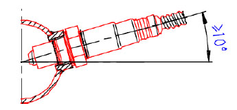
Sensor should be placed at an angle greater than 10 degrees from horizontal as shown in picture below. Allows for water to NOT accumulate around the sensor.
Make sure to mark the location of the O2 bung to be welded in before removing the exhaust pipe from the vehicle. We highly suggest installing a new exhaust pipe on the vehicle before taking a guess of where the O2 bung should be welded. Space is limited on a number of applications. Make sure to inspect the Bosch O2 sensor to get an idea of the space required to install the sensor into the O2 bung.
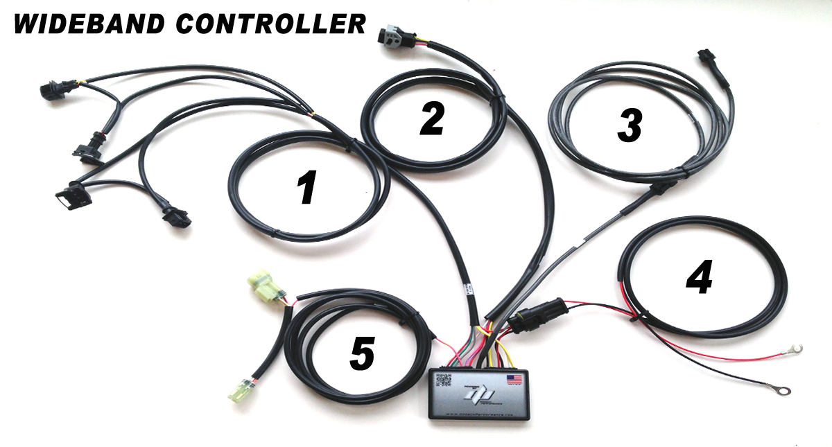
All DP wideband controllers come with at least four different connections and sometimes five. The first step is to identify the different harness connections before attempting the installation.
Stock Fuel Injector Connector(s) - Plugs into the factory injector connection(s) or a sub-harness connection to create loop around to adjust the fueling. Connector varies based on application. One male & female pair for each cylinder unless a sub-harness connection is used for easier installation.
Bosch O2 Connector - Plugs into the installed wideband Bosch O2 Sensor in the exhaust pipe.
AFR Gauge Connector - Single long gray wire which plugs into the AFR Gauge for easy installation. Additional harness may be purchased to extend the connection even further.
Power & Ground Wire - RED wire is a 12V POWER source for only the Bosch O2 sensor and connects on most applications to the battery. BLACK 16 AWG wire is the ground wire and RECOMMENDED to attach to the standard grounding location on the frame of the vehicle. Click here to see an example common vehicle ground
Stock O2 Connector(s) - OPTIONAL - Plugs into the stock O2 connection going back to the ECU. Connector varies based on application and may NOT be present.
GENERIC INSTALL STEPS:
MOUNT - Determine the best location to mount the wideband controller using the supplied Velcro patch. The wideband controller DOES NOT need to be accessible. Typical mounting locations are under the seat, next to the battery, inside a side cover, etc.
GROUND - Connect the BLACK ground lead wire coming from the wideband controller to the negative side of the battery or to the vehicle's general grounding location. The silver terminal end can be cut open to fit around the terminal or frame bolt.
INJECTORS - Remove necessary components to access the fuel injector(s) or the sub-harness connection. Please consult your owner's manual. Route the injector harness as needed to go from your mounting location to the injectors. Make sure to keep the harness away from hot and moving parts. Use zip ties as needed to attach to the frame. Unplug factory connection(s) and plug the matching wideband connections back into the factory connections.
AFR GAUGE LEAD - Route the single GRAY wire for the AFR gauge up through the frame to your gauge mounting location. The GREY wire will connect through small BLACK 6 pin connectors. Use zip ties as needed to attach to the frame.
BOSCH O2 SENSOR LEAD - Route the single BLACK harness with the large BLACK 8 pin connector to the installed Bosch wideband O2 sensor. Use zip ties as needed to attach to the frame.
FACTORY O2 CONNECTIONS - OPTIONAL - If your vehicle is equipped with factory narrowband O2 sensors then you will need to do one of the following:
Leave the factory O2 connections intact.
Simply disconnect the factory O2 connections and zip tie them out of the way.
Disconnect the factory O2 connections and install the supplied O2 bypasses.
Route the wideband factory O2 harness as needed to go from your mounting location to the factory narrowband connections.
START VEHICLE - Always attempt to START your vehicle before re-assembling removed pieces. DO NOT SIMPLY TURN THE KEY ON!!
Installation of the AFR gauge is left up to end user preference. Dobeck supplies some basic hardware in every AFR+ kit for connecting to the back of the gauge. The AFR gauge is the industry standard size of 2-1/16" to allow for a number of after-market gauge mounts to be used.


